How Vacuum Thermoforming Transforms Plastic Manufacturing
Introduction to Vacuum Thermoforming: Principles and Terminology
This article introduces the basic principles and relevant terminology of vacuum thermoforming, helping readers understand how the thermoforming process works.
1. Principle of Vacuum Thermoforming
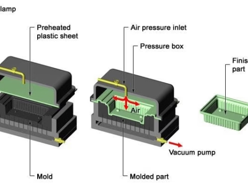
Vacuum thermoforming is a heat forming process that uses thermoplastic sheets to create open shell products. The process involves cutting the plastic sheets to a specific size, heating them to soften, and then using a pressure difference or mechanical pressure on both sides of the sheet to shape it and make it adhere to a specific mold. Afterward, the product is cooled and trimmed.
This forming method relies on vacuum force to stretch and deform the sheet. The vacuum force is easy to implement, control, and adjust, making simple vacuum forming the earliest and most widely used method in thermoforming.

2. Vacuum No-Mold Forming
The process of vacuum no-mold forming is shown in Fig. 2-2. The sheet is heated to the required temperature, placed on a clamping ring, and then compressed by a pressing ring. The vacuum pump valve is opened to extract air, with the vacuum level controlled by a photoelectric tube. This continues until the sheet reaches the desired depth of formation. Since the product does not touch any mold surface in this method, it has a high gloss finish without defects. If the plastic is transparent, the product will have minimal light absorption and transparency, making it suitable for parts such as instrument covers and sunroofs in aircraft.
However, vacuum no-mold forming can only change the stretching extent and shape of the part’s outline and is unsuitable for complex shapes. Additionally, as stretching increases, the thickness at the center of the sheet decreases, so in actual production, the stretching ratio (H/D) should generally be less than 75%.
Skilled operators are required to adjust the vacuum level to achieve the desired contours and dimensional consistency.
3. Vacuum Forming with Male (Convex) and Female (Concave) Molds
In vacuum thermoforming, the heated material only contacts one side of the mold. This means that the side of the material that touches the mold will have the exact surface contour of the mold. The shape and dimensions of the non-contact side depend solely on the material’s thickness. The forming process can be divided into male mold (convex) and female mold (concave) forming depending on which side of the mold the material touches.

Mouldless vacuum forming device

Wall thickness distribution of moldless vacuum forming
| Forming Mold | Single Male Mold | Single Female Mold | Forming Assisted by Plunger |
|---|---|---|---|
| Allowable Stretch Ratio | >0.5 | >1 | >1 |
Table – Allowable stretch ratios for different molds
Male Mold Forming
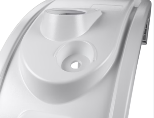
The vacuum male mold forming process is illustrated in Fig. 2-4. This method is advantageous for producing products with large wall thicknesses and depths. The main features of the products are: the side in contact with the mold cavity has higher quality and finer details, with the thickest part at the top of the male mold and the thinnest part at the intersection of the side and bottom of the mold. This area is the last to form, and products often have stretch marks and cooling streaks on the sides due to the cooling process.

2-4
Female Mold Forming
The vacuum female mold forming process is shown in Fig. 2-5. The products formed by this method also have fine details and higher quality on the mold-cavity-contacting surface, with the thickest part at the bottom of the cavity and the thinnest at the intersection of the side and bottom. As the cavity depth increases, the thickness at the corners of the product's bottom becomes thinner. Therefore, this method is not suitable for producing very deep products.

2-5
For male mold forming, the inner dimensions of the product are highly precise as they are in direct contact with the thermoforming tool. On the other hand, for female mold forming, the outer dimensions are more precise, as the outer surface is in contact with the mold.

1-thick part; 2-thin part; 3-inner size of finished product; 4-outer size
Issues with Male Mold Forming
- When using molds with high corner angles, especially when the distance between the mold and the clamping frame is large, wrinkles may form.
- Cooling streaks often appear at the corners.
- Uneven wall thickness at the flange.
- Difficulty in mold release due to insufficient sidewall slope.
- Small gaps may form between the insert and the clamping frame.
- Thicker edges.
- Uniform edge thickness.
- Thinner corners.
- Female molds generally have better mold release.
- Female molds are typically more expensive than male molds. However, most of the adverse effects can be minimized by using the appropriate processing methods.

1-Cooling marks; 2-Wrinkles; 3-Thin parts; 4-Thick parts

1-Uniform Edge; 2.Thin Corner
4. Basic Equipment for Thermoforming Machines
1.Clamping Equipment
During thermoforming, the plastic sheet is fixed in place using clamping devices. In general-purpose and composite thermoforming machines, clamping devices that accommodate various sheet sizes are used. These can either be frame-type or petal-type.
2.Heating Equipment
One of the primary processes in thermoforming is heating the thermoplastic sheets to a soft, moldable state. Common heating equipment includes electric heaters, crystal radiators, and infrared heaters.
3.Vacuum Equipment
The vacuum system consists of vacuum pumps, storage tanks, valves, pipes, and vacuum gauges. Thermoforming typically uses dedicated vacuum pumps, with a vacuum pressure of 0.07–0.09 MPa (520mmHg) or higher.
4.Compressed Air Equipment
Pneumatic systems in thermoforming machines include compressors, storage tanks, and air supply valves, providing compressed air at 0.6–0.7 MPa.
5.Cooling Equipment
To improve production efficiency, products are often cooled before being released from the mold. Cooling can be done using internal cooling coils in the mold or external air or water cooling.
6.Mold Release Equipment
Mold release is performed using mechanical means or through the application of air pressure to detach the formed product from the mold surface.
7.Control Equipment
The control system manages various parameters in the thermoforming process, including vacuum levels, temperature, and pressure, through manual, electric-mechanical, or computer-controlled systems.
5. Effective Forming Pressure in Thermoforming
The precision of a vacuum-formed product primarily depends on the effective contact pressure between the heated sheet and the mold. Effective forming pressure combines the contact pressure generated during pre-stretching and the forming pressure created by vacuum or mechanical pressure from the plunger. In other regions, the material does not contact the mold, and the effective contact pressure is determined by the difference between the forming pressure and the reverse pressure from the material.
For male mold forming, typical forming pressures are 0.2–0.3 MPa (2–3 bar) for large parts, and up to 0.7 MPa (7 bar) for smaller parts. For vacuum forming, forming pressures are relatively low and mainly dependent on atmospheric pressure.

6. Thermoforming Area, Cutting Area, and Clamping Edges
The area within the clamping frame is referred to as the forming area. The cutting area refers to the area where stretching occurs during forming. The clamping edge must be heated to above the glass transition temperature (Tg) of the material if the edge is not to be cut immediately after molding.

7. Thermoforming Waste Area and Waste Ratio
Managing waste material is critical for cost control. The waste area typically includes the clamping edge area and the material leftover after forming.
Example:
- Initial sheet size:610 mm x 1200 mm
- Formed product size (after trimming):440 mm x 960 mm
- Waste ratio calculation:4%
Forming Area and Cutting Area
- a. For male mold forming, the forming area is equal to the cutting area.
- b. In vacuum male mold forming, the cutting area is reduced due to the effect of the additional protective element.
- c. In female mold forming, the processing cutting area is specified.
L · B – Forming Area
L1 · B1 – Cutting Area
? – Clamping Edge
E – Stretch Start Point in Male Mold Forming (where wall thickness changes)
Figure 2-12: Diagram of Rectangular Box Material Product (Right Side shows the Finished Product after Trimming)
AB – Mold Bottom Surface
C – Height
L1 and L2 – Length of Mold Extension to Sheet Edge
D – Clamping Edge


Waste Material of Sheets
The waste material of the sheet consists of the clamping edge area and the leftover material after forming and stretching the product. The primary focus is on calculating the amount of edge material remaining after stretching and forming the product.
Note: Vacuum Forming Cutting Area – The trim area of the product.
Calculation Based on the Following Formula:
Forming/Mold Area = (610−20×2)(1200−20×2)(430×950+430×200×2+950×200×2)+[(610−20×2)(1200−20×2)−430×950]\frac
= 66120 / 1174720 = 0.056
Waste Area = 0.056 × [(610 – 20×2)(1200 – 20×2) – 440×960] + [610×1200 – (610 – 20×2)(1200 – 20×2)] = 142353.2 mm²
Waste Ratio = 142353.2 / (610×1200) = 0.194 or 19.4%
8. Venting Holes and Grooves in Thermoforming
To remove trapped air between the material and the mold during vacuum forming, molds must be designed with venting holes or grooves to allow air to escape.
9. Mold Draft Angle
The mold draft angle is the angle required for the mold sidewalls to facilitate the easy removal of the formed product. The draft angle should be as large as possible to prevent deformation during release and reduce forming time.
 X. Vacuum Forming Ratio and Stretch Ratio