
Stop thinking of the vacuum forming process as a hobbyist’s craft. If you are designing large plastic parts for a medical diagnostic housing, an agricultural vehicle shroud, or an aircraft interior panel, you are dealing with real-world thermodynamics and fluid mechanics. In this guide, you will learn the exact physical laws, tooling constraints, and machining realities required to scale heavy-gauge thermoforming. As a leading custom plastic manufacturing specialist and thermoforming manufacturer, トップ熱成形 manages the complex interplay of heat, vacuum pressure, and tooling geometry to produce industrial-grade components. Let us break down the exact physics of how we transform flat sheets into high-precision structural parts.
Key Takeaways for Hardware Engineers:
- Atmospheric pressure (14.7 psi) is the actual force driving the forming process, not the vacuum pump alone.
- Aluminum tooling with integrated water-cooling lines is non-negotiable for dimensional stability and preventing part warpage.
- 5-axis CNC routing is the only reliable method to achieve repeatable ±0.030″ post-forming tolerances.
- Draw ratios must be managed early in the CAD stage to avoid catastrophic wall thinning and webbed corners.
Why Does Atmospheric Pressure Control the Industrial Vacuum Forming Process?
Many product designers believe that a vacuum pump actively sucks a molten plastic sheet into the corners of a mold. That is mechanically incorrect. The vacuum pump does only one job: it evacuates the air trapped between the heated thermoplastic sheet and the mold surface. This creates a low-pressure void. Once that void is established, the real work is done by the ambient atmosphere. The 14.7 pounds per square inch (psi) of atmospheric pressure pressing down on the exposed side of the sheet crushes the pliable plastic into the tool’s geometry.
Think about the math. If you are forming a large plastic part, say a utility vehicle roof measuring 5 feet by 8 feet, you have 5,760 square inches of surface area. At a full vacuum, the atmosphere exerts over 84,000 pounds of force across that sheet. This massive, uniform pressure forces the hot polymer chains to conform to the micro-textures machined into our aluminum tooling. But this force is only effective if the material is at its precise forming temperature. If the sheet is too cold, the 14.7 psi will fail to register the fine details. If it is too hot, the plastic will tear, sag excessively, or suffer from thermal degradation.
This is why high-volume custom plastic manufacturing requires massive, industrial-grade vacuum reservoirs and high-flow valves. We do not slowly draw the air out. We dump the vacuum instantly. This rapid evacuation ensures that the atmospheric pressure slaps the plastic against the mold before the material has a chance to chill against the cold metal. Speed is everything when managing thin-gauge or highly conductive polymers.
How Do We Control Thermodynamics in Heavy-Gauge Sheet Heating?
Thermoplastics are poor thermal conductors. This physical reality makes heating a thick sheet of ABS, Polycarbonate, or HDPE a delicate balancing act. If you blast a 0.250-inch-thick sheet of plastic with high heat from one side, you will scorch the surface long before the core of the sheet reaches its glass transition temperature. To prevent this, Top Thermoforming utilizes multi-zone, ceramic infrared heaters controlled by programmable logic controllers (PLCs) and non-contact pyrometers.
We heat the sheet from both the top and bottom simultaneously. This sandwich heating method ensures a uniform temperature gradient throughout the cross-section of the material. Different polymers have narrow thermal windows. For example, high-impact ABS requires a forming temperature between 320°F and 380°F. If you fall below this, you introduce molded-in stress that will cause the part to crack later in the field. Go above it, and the material begins to break down chemically, leading to cosmetic defects like blistering or pinholes. We monitor the thermal properties and melt flow behavior of our materials to align with recognized ASTM International standards for plastics characterization, ensuring structural integrity across every production run.
During the heating cycle, the sheet will sag under its own weight. This is called sheet sag, and it is a natural consequence of gravity acting on a viscoelastic fluid. Our machines use photoelectric sensors to monitor this sag. If the sheet sags too far, the machine injects a small cushion of air beneath the sheet—a process called “bubble blowing”—to support the material and prevent it from touching the lower oven elements. This level of control is what separates a professional thermoforming manufacturer from a low-cost prototype shop.
Why Is Tooling Design the Real Secret to Large Plastic Parts?
You cannot make a high-precision plastic part on a cheap tool. While wood, MDF, and epoxy tooling are acceptable for proof-of-concept prototypes, they are useless for production. They act as thermal insulators. They trap heat, which means the tool gets hotter with every cycle. This thermal buildup slows down your cycle times and causes massive dimensional variation from part to part.
For production-grade custom plastic manufacturing, we design and CNC-machine temperature-controlled aluminum molds. Aluminum has excellent thermal conductivity. We gun-drill water lines directly through the aluminum tool body and connect them to a Temperature Control Unit (TCU). This TCU pumps water at a constant, calculated temperature through the mold. By keeping the tool at a precise temperature—typically between 120°F and 180°F depending on the resin—we freeze the plastic at a controlled rate. This eliminates warping, reduces internal stress, and keeps cycle times highly predictable.
Draft Angles: The Mechanical Reality of Part Release
Plastics shrink as they cool. Amorphous materials like ABS shrink at a rate of roughly 0.005 inches per inch, while semi-crystalline materials like HDPE can shrink up to 0.020 inches per inch. If you are forming a female cavity (where the plastic is drawn into a pocket), the material will shrink away from the mold walls, making ejection easy. However, if you are forming a male mold (where the plastic shrinks onto a raised block), the cooling plastic will grip the aluminum like a vise.
Without proper draft angles, you cannot get the part off the tool without destroying it. We require a minimum of 2 to 3 degrees of draft on male molds, and ideally more for textured surfaces. If your part has zero draft, we will refuse to run it until the CAD is modified. It is not because we want to change your design; it is because the laws of thermal contraction are non-negotiable.
How Do 5-Axis CNC Routers Achieve Repeatable ±0.030″ Tolerances?
A vacuum-formed part straight off the mold is a raw, unfinished shell surrounded by a flange of excess material. It is functionally useless until it undergoes post-mold trimming. At Top Thermoforming, we do not allow operators to trim heavy-gauge parts with hand routers or band saws. Manual trimming yields sloppy, inconsistent edges and makes achieving tight tolerances impossible.
Instead, we transfer the cooled plastic shell to our high-speed, 5-axis robotic CNC routing centers. These machines use rigid, vacuum-clamping fixtures to hold the formed part securely in place. The 5-axis capability allows the cutting spindle to move fluidly around complex, 3D geometries, maintaining a perpendicular angle to the part surface at all times. This is how we cut mounting holes, slot vents, and perimeter profiles with a repeatable tolerance of ±0.030 inches.
To maintain this accuracy, we must engineer the trimming fixtures with the same care as the forming molds. The fixture must match the B-side of the plastic part perfectly, preventing any vibration or deflection while the high-speed carbide router bit cuts through the material. If the part vibrates during machining, you get rough, scalloped edges and out-of-tolerance holes. Our engineering team designs these fixtures in-house using the same 3D CAD data used to cut the molds, ensuring perfect alignment between the formed shape and the machined features.
What Are the Economic Realities of Vacuum Forming vs. Injection Molding?
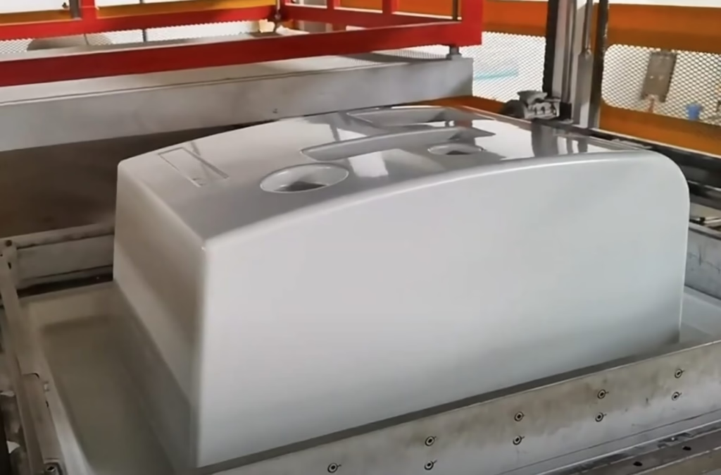
When you need to manufacture large plastic parts, you generally choose between vacuum forming and injection molding. The decision comes down to part size, annual volume, and upfront tooling budget. Injection molding requires two matched, high-pressure steel mold halves that must withstand tens of thousands of pounds of clamping force. This means a single injection mold for a large part can easily cost $150,000 to $500,000 and take 16 weeks to build.
In contrast, vacuum forming is a single-sided, low-pressure process. Because we are only dealing with 14.7 psi of atmospheric pressure, our molds do not need to be massive steel blocks. We can cast or machine them from aluminum at a fraction of the cost—typically between $15,000 and $50,000. Tooling lead times are also cut in half, often taking only 1 to 2 weeks. This drastically accelerates your speed to market.
While the piece-price of an injection-molded part is lower due to faster cycle times, the break-even point for vacuum forming often extends into several thousand parts per year. For low-to-medium volume runs—ranging from 250 to 5,000 parts annually—vacuum forming is almost always the more economical choice. This is especially true for large-scale components like medical cart enclosures, heavy equipment cabs, and industrial housings where the tooling cost of injection molding is financially unjustifiable.
Frequently Asked Questions
Q1: What is the maximum “draw ratio” in the vacuum forming process?
We strongly advise designers not to exceed a 3:1 draw ratio (depth to width) without utilizing mechanical plug assists. Pushing past this limit naturally results in severe wall thinning and webbed corners. If you design a deep, narrow pocket, the plastic sheet will stretch excessively, leaving you with paper-thin walls at the bottom of the cavity. By using a plug assist—a mechanical plunger that pushes the plastic into the mold before the vacuum is applied—we can distribute the material more evenly, but the 3:1 rule remains our baseline limit for structural integrity.
Q2: Does vacuum forming leave tool marks on the final plastic part?
Only on the tool side (the A-side). The B-side facing the atmosphere remains perfectly smooth or retains the original textured finish of the extruded sheet. We polish our aluminum tools extensively to prevent any mechanical transfer marks. However, any imperfection on the mold surface—such as a machining line, a vent hole, or a speck of dust—will transfer directly to the contact side of the plastic. This is why we pay meticulous attention to mold finish and cleanliness on our production floor.
Q3: Can vacuum forming handle undercuts on complex geometries?
Yes, but it requires articulated tooling. We integrate pneumatic side-actions or collapsible aluminum cores into the mold. It adds to the tooling cost but is still a fraction of the price of an injection mold slide action. When the forming cycle is complete and the plastic has cooled, these pneumatic inserts retract inward, allowing the part to clear the undercut and release from the mold without tearing or distorting.
Q4: What materials do you recommend for medical and aerospace housings?
We form heavy-duty engineering-grade thermoplastics. For EU and US compliance, we strictly use UL94 V-0 flame-retardant materials like Kydex, high-impact Polycarbonate, and specialized ABS blends. These materials offer exceptional impact resistance, chemical resistance to harsh disinfectants, and meet stringent flammability and smoke emission standards required for public transit, aircraft interiors, and clinical medical environments.
Q5: How do you prevent the plastic sheet from chilling too fast on the mold?
We don’t use cheap wooden tools. We CNC machine aluminum molds with internal water-cooling lines and temperature control units (TCUs) to maintain exact mold temperatures, ensuring the plastic sets perfectly without warping. By keeping the mold at an optimized temperature, we prevent thermal shock, which occurs when hot plastic hits a cold surface. This ensures the polymer chains relax into the mold shape uniformly, preventing molded-in stress.
Q6: How much vacuum pressure is actually applied during forming?
Industrial vacuum pumps pull nearly a perfect vacuum inside the mold cavity. This allows the heavy lifting to be done by the atmosphere, which presses down on the heated sheet with roughly 14.7 pounds per square inch of force. This pressure is highly consistent and uniform, ensuring that even large, complex parts receive equal forming force across every square inch of their geometry.
Q7: Why partner with Top Thermoforming instead of a local prototype shop?
Scalability and precision. Local shops struggle with thick-gauge repeatability. We manage the entire lifecycle—from in-house aluminum tooling to 5-axis CNC trimming—ensuring your parts meet strict US and CE regulatory standards on a commercial scale. We don’t guess at process parameters; we run a highly calibrated, data-driven production floor designed for medium-to-high volume manufacturing.
Stop guessing about draft angles, material selection, and draw ratios. If you want to avoid costly design iterations and production delays, you need to design for the physics of the process from day one. Send your 3D CAD files to トップ熱成形 today, and our engineering team will analyze your geometry to optimize your parts for the industrial vacuum forming process.
 JA
JA  EN
EN  IT
IT  DE
DE  FR
FR  ES
ES  PL
PL  NL
NL